“Snap-Fit” Puzzle Pieces – A CAD Design Project to Teach Kids How to Measure and Design to Tight Specs

My students come to me with all sorts of brilliant ideas for things to create, and are very adept at designing parts for them to be 3D printed, laser cut, or fabricated in some other way. One thing that often gets in their way is measurement and placement of structures and holes in their parts to allow them to attach to other parts made by the student or from some other source (like microcontrollers, lights, LCD screens, etc…) This activity is designed as a fun and challenging way to give them practice in this skill set.

My students come to me with all sorts of brilliant ideas for things to create, and are very adept at designing parts for them to be 3D printed, laser cut, or fabricated in some other way. One thing that often gets in their way is measurement and placement of structures and holes in their parts to allow them to attach to other parts made by the student or from some other source (like microcontrollers, lights, LCD screens, etc…) This activity is designed as a fun and challenging way to give them practice in this skill set.

Setting Up

You can do this activity in any 3D design tool that allows you to accurately control creation and placement of objects to 1mm, although .1mm would be better. I have had students successfully complete it using Tinkercad and Fusion360. In addition, make sure your students have experience using calipers to accurately measure real world objects. The power of this activity is that students measure things in the real world (don’t give them the files you use to create them!) and have to design around them. You don’t need expensive digitals calipers, or even metal ones. This set of 2 plastic calipers or this set of 4 plastic calipers will both work. You are better buying enough inexpensive calipers for your entire class than a few expensive ones to be shared.

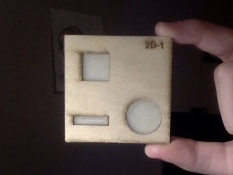
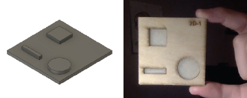
  • You need a set of target pieces, the more the better. Kids will need to be hands on while measuring and designing these blocks. Make sure you have at least one for every two kids, but 1:1 is better. If you have access to a laser cutter, cutting them from 1/8 plywood has worked best for me, but 3d printing them will work as well. There are 5 different pieces. You can download the files from this Instructable.
    • Adobe Illustrator File (for laser with four copies of each of the five files )
    • .svg File (for laser)
    • .stl files (one for each of the 5 different pieces)
  • Calipers as described above 1:2 or 1:1 if possible.
  • Access to Tinkercad, Fusion360, or other 3d design software
  • Graph paper and rulers – I have found that most kids (and adults) who don’t have much experience designing something like this will do better if they can start on paper before they get to the computer.
  • 3D printers ready to go!

Activity Plan

  1. Hand out the target blocks and let students “play” with them a bit and become comfortable with their details.
  2. Hand out graph paper and ask students to sketch (to scale) and label dimensions of their part. Explain to them that:
    1. they will need to measure the shapes and reproduce them in their sketch
    2. they will also need to measure the positions of the shapes – based on a corner or a center point, depending on the shape
  3. Once they have accurately sketched their object, have them trade objects with a partner and have each student check the other’s work.
  4. Now you need to make a decision on how to go forward, largely based on how much time you have and how many 3d printers you have access to .
    1. The best option is send students to their CAD software and tell them only: “Create a part that you can 3D Print and will snap perfectly into the target part you were given.” This route will result in failures, some frustration, and a few iterations (ie. multiple prints per student). They will have to discover the best way to do this, and they will gain more from the process.
    2. If time and equipment won’t allow the first option, then you will need to give them a few hints. Tell them:
      1. The shapes will need to be as tall as the target blocks so that they fit in well.
      2. The shapes need to be a little bit smaller than the shapes in the target blocks – like .05mm or they won’t snap in well. This number might be different depending on your printer settings, so you might want to try this activity first to test out you printers.
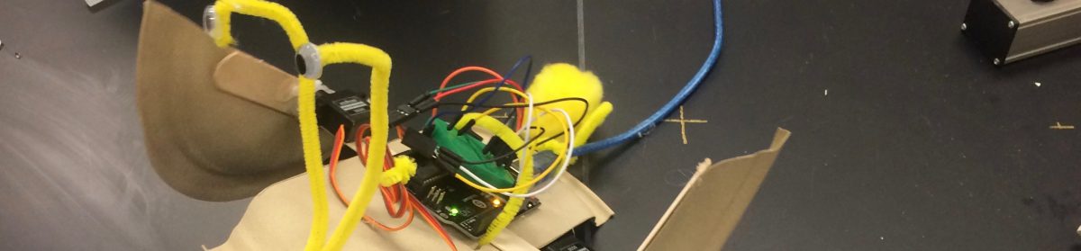
  5. At this point the students need to design and print their piece. Support them, encourage them, and make it ok for them to struggle a bit! The first student to print one that snaps in will be excited and encourage the others. Don’t let them give up!

2d3d Project Notes – 1 Student Logos

Last year I was asked to come up with some suggestions for new 9-week long wheel classes for Pine Crest Boca 7th and 8th graders. The first one to come to mind was something I had been wishing for over the last few years – a course to teach students to create for and use the laser cutter, 3D printers, and other fabrication equipment we have in the iLab. In the three years since the iLab opened, much of the student’s learning of the fabrication machines and the software used for designing on them has been “just in time” – given to them when they needed it for a class or individual project. Therefore the instruction has been somewhat limited and very uneven when you look at the set of students in the lab over this time. An elective wheel class would go a long way towards fixing this.

As the curriculum and logistics for the course were figured out last spring, one 7th grade class turned into two classes with the edition of an 8th grade section (for this year only, available to this year’s 8th graders so they would get a chance to take it) and a series of projects were sketched out to focus the curriculum on. We were fortunate to bring in Ashley Becker as a new CompSci / Tech teacher with a wealth of training and professional experience in 2D design and specifically in Adobe Illustrator – something I was personally lacking. Her 2D and general design expertise along with my 3d CAD and fabrication machine experience have made us a great team, as she teaches the 7th graders and I teach the 8th graders.

From the beginning I wanted the curriculum to be based on a series of projects to be produced on the fabrication machines (run by the students), starting with 2D, and finishing in 3D. Learning to design and fabricate using vector-based software would be the common thread through the course. Students will hopefully leave with the basic skill set to allow them to make almost anything they wanted with these machines (laser, 3d printer, CNCs, vinyl cutters, plotter….) and carry these skills to the iLab in PCFL’s Upper School, and whatever makerspace they have access to in college.

So starting with this post I’ll share some notes and impressions on each project with the hopes that our ideas can help other in the MakerEd community and that the community will continue to educate and inspire us!

The first project was for students to create logos for themselves using the basic Adobe Illustrator tools that we had taught during the first week or so of class. These include basic shape and text objects, pen tools, the manipulation of anchor points, and the use of layers to organize and control your work. These logos could continue to be used (as students wished to) throughout the rest of the class. We avoided using bitmap grapics in the final design, and in the desire for simplicity we told students that they could import in a simple bitmap and trace it using pen tools to replicate a graphic and then modify it for their own logo. No Image Trace for this first project.

This is a relatively simple project, one I’ve seen others do online and that I’ve done myself with much younger students so it seems like a good starting point.

The logos would be fabricated using Cameo Silhouettes, using colors of paper based on the colors / layers students used in their designs. Cameos are great starter tools for fabrication. You have to think about size, layouts, layers, cutting vs sketching, and other factors that translate well to designing for more advanced fabrication tools. They are cheap, so we have a small set of them to speed up student use.

The logos and resulting builds were amazing, and the kids were obviously proud of their work. Layers were a struggle for some students, but this was a great project to show their use and importance and move students towards using layers regularly and with skill. For a simple project, much was learned and the students were ready for the next steps.

Micro:bit “Hello World”

If you have used MakeCode with the Circuit Playground Express, switching over to the Micro:bit will be a breeze! They are pretty much programmed the same way, and you transfer your code to the Micro:bit just like you do with the CPX. In this Recipe we will play with the Micro:bit, focusing on a few of the differences in its capabilities, notably its display and radio features – both of which are very useful for many project ideas your student will come up with!

Ingredients


Directions

  1. Go to makecode.microbit.org and create a new project. At the bottom of the screen, name the project “Hello Radio” and click the save icon.
  2. From the “Input” set of blocks, drag an on button A pressed event out.
  3. From the “Basic” set, drag a show string block out and place it inside the event block. Change the string to “Hello World”. Test the button on the simulator, then download and move the file to the Micro:bit board to test it there.Hello_Radio_-_makecode_microbit_org.png
  4. Now create a second event so that when the B button is pressed you get the message “Goodbye!”. Test on the simulator.
  5. Now we are going to add the radio function. You will need to work together with a partner for this one.  From the “Radio” blocks, take a radio set group block and place it in the on start event. If you are doing this with only one other person, you can leave the group as 1 but if you are doing this with a class with multiple teams then each team should use a different number.
  6. Make the changes and add new radio blocks as shown below so that the A and B buttons send messages with your name to any other Micro:bits in your group, and when you receive a message it displays it. Hello_Radio_-_makecode_microbit_org.png
  7. Download the code and test it with your friend. See if you can send messages to each other!


Hello World Garnishes

  • Icons! They are easy to select or make yourself using the show leds and show icon blocks in the “Basic” tools.
  • Can you change your radio program above to send icons to your friend? How about creating a game (like rock, paper, scissors) that you can play with two Micro:bits? A coin flipper? A reaction time game? If you need help or ideas, there are some amazing projects laid out at https://makecode.microbit.org/projects

Micro:bit Neopixel Numberline Recipe: Basic +/-

Vn Start this recipe by creating your own copy of MBnumberline Engine 1 by clicking on the link below. It will open in a new tab and you can switch back and forth to these instructions.

https://makecode.microbit.org/_2A5fviDXmeLg

Think of this code as a basic function to display whatever you place in the variable NumberLineValue on your number line. Now you just need to add your own code to make create math problems or other functions.

  1. Once you open the link above, click the big pink “Edit” button at the top to start adding your own code.
  2. For our this first example, we will program the four buttons available to you (Button A, B, pin 1 and pin 2) to add and subtract numbers as well as clear the number line back to 0. To begin, we will create an On Button A Pressed event.
    1. From the Input blocks, pull an On Button A Pressed block out to the code area. We want the B button (because it is on the right side) to add 1 to the number line, so change the A in the block you pulled out to a B.
    2. To add 1 to the number line, go to the Variables blocks and pull out Change #### Value by 1.  You will then set the variable to NumberLineValue. Test it in the simulator on the right, then upload it to test on the number line.
    3. When testing, see what happens when you keep pressing the B button more than 20 times. How will we fix this?
    4. We need to add an if-then block to test if the number is over 20. If it is, we will just change the number back to 20 so it doesn’t go off of the number line. From the Logic blocks, drag an if-then block out and place it under the Change value block. Also from the Logic blocks you will need a < conditional block to be placed in the spot right after “if“.  Change the < to a >, from Variables drag a NumberLineValue block and place it before the >, and change the “0” to a 20 after the >. The If statement will now read” If NumberLineValue > 20.
    5. In the space after then, go to the Variables blocks and grab a Set NumberLineValue to block and change the value to 20. Now if you go over 20, your variable will just go back to 20. Download and test!
      Number_Line_Engine_v2_-_makecode_microbit_org.png
  3. Now that you can add 1, wouldn’t it be nice to be able to quickly clear back to 0 and reset everything? We will code your number line so that pressing A&B at the same time will set the NumberLineValue variable right to 0. This one is pretty easy:
    1. From the Input blocks, pull an On Button A Pressed block out to the code area. Change A to A&B.
    2. From Variables grab a set NumberLineValue to block and leave the value to zero, placing it in the On Button A&B Pressed event.
    3. Download and test!
      Number_Line_Engine_v2_-_makecode_microbit_org.png
  4. To finish up, we need to program the A, 1, and 2 buttons so that:
    1. The A button will subtract 1
    2. The 1 button will subtract 5
    3. The 2 button will add 5

      This will be simplified by copying your first chunk of code (The on button B pressed code) and making the few, small changes needed to get it working. To copy the chunk of code, just right-click on the pink on button pressed event and chose duplicate. Than make changes needed, starting with which button you are coding, to make it work properly. Good luck!

Circuit Playground Express Input / Output “Snacks”

These snacks are best attempted after you have completed the Hello World and Basic Input /  Output recipes. The snacks are designed to open up the many possibilities of the sensors built into the CPE. Instead of walking you through each one, I’ll just present a description and the code for you to try. Please mess with / tweak / and expand on the given code – that’s where the fun and the learning happen!

There are some new blocks here, blocks we didn’t cover in the first recipes in this series. Don’t worry, all you need to do is find which set of blocks they belong to (by matching the colors) and set them up the way they are in the picture. Before

Snack 1

This code will use the built-in microphone to react when it hears a “loud sound”.

Clap_Back_-_Microsoft_MakeCode.png

https://makecode.com/_WxJEJzYD1Rge


Snack 2

Buttons A and B will rotate and reverse the direction of light pattern on the built in neopixels.

rotate_lights_button_-_Adafruit_Circuit_Playground_Express.png

https://makecode.com/_VqrJJ8099d3z


Snack 3

We will use the built in accelerometer as a “tilt sensor” to control some of the Neopixels. We are going to use some nested if else blocks, so I’ll show you how to build it in steps.

  1. Nest 2 if else blocks together inside of the forever loop. Everything else will end up inside of them.
    Screen Shot 2018-01-25 at 10.19.16 AM.png
  2. From the Logic blocks add the inequality statement to the first if statement checking to see if the x accelerometer is greater than 100 (it ranges from 0 when the board is flat to 1023 when it is tilted 90 degrees to the ground.  Then add a show ring block, and light up the right lights to show it is tilting right.
    Screen Shot 2018-01-25 at 10.23.00 AM.png
  3. Finish up by setting the second if opposite of the first (inequality and number) and set the lights opposite as well. Add one more show ring and set all of the lights to neutral to show that the board is flat.
    Screen Shot 2018-01-25 at 10.23.43 AM.png
  4. Upload and you are done!


Snack Mix!

Create your own snack! Mix together the skills from all of the snacks to create your own interactive project. Add sounds, animations, and different combinations of sensors. Can you make it do something when the board drops? What about making the lights go on when it gets dark? Play and have fun!

Circuit Playground Express “Hello World”

“Hello World” refers to the first program you write on a platform or in a programming language you have never used before. This recipe is a Hello World using the Neopixel LEDs built into the Circuit Playground Express, with a few extra garnishes thrown in.

Ingredients


Directions

  1. Go to http://makecode.adafruit.com and start a new project.
  2. On the workspace, you should find a green forever block. Anything you place inside of it will repeat as long as the CPE is powered on.
  3. From the “Lights” set of blocks, select show animation and place it inside of the forever block. Select which of the six pre-set animations you want.
    Untitled_-_Adafruit_Circuit_Playground_Express.png
  4. On the left side of the screen there is a simulation of how your code will run on the real CPE. Check it out, and change the “ms” setting from 500 milliseconds to some other number to see what it does to the animation.
  5. Name the file. Look for the field in the bottom center with the floppy disk image next to it. You can call it “HelloWorld” or whatever else you like. After typing, click the floppy disk Save icon.
  6. Finally, the most technical part – sending your code into the actual CPE. The good news is that you will repeat this part each time you change or write new code so it will become rote and simple for you soon!
    1. Click the big Download button at the bottom left of the screen.
    2. Your code will download, probably into your “Downloads” folder. In Google Chrome (and other browsers) you can click the triangle next to the file you downloaded and choose “Show in Finder” to find it in your downloads folder.
    3. Plug the Micro USB cable into your CPE and into your computer.
    4. Click the reset button on the CPE. The lights should turn red then stay green, and the board will be in programming mode. Your computer will think it is a USB Drive named CPLAYBOOT.
    5. Drag the downloaded file (it will have whatever you named it in the file name) to the CPLAYBOOT disk. The file will transfer and then your program should start running on the CPE!


Garnishes

What else can you throw into the forever loop? Try some things from below, following step 6 each time to transfer your updated code to the CPE board for testing.

  • There are other options in the “Lights” blocks. You can change colors in the show ring block by clicking a new color from the center and then clicking an individual light to change its color. Alternating show ring blocks and pause blocks from the “Loops” set will let you create your own animations.
  • Check out the sounds and notes available in the “Music” set of blocks. Try adding one or more of the available sounds to your loop.


Circuit Playground Express Basic Input-Output

The real power of microcontrollers is in using them to give outputs to lights, speakers, motors, or pretty much any other electronic device based on inputs given to them from buttons, keyboards, sensors, etc…  In this recipe, we will experiment with basic inputs and outputs on the Circuit Playground Express (CPE) using only its onboard sensors, lights and speakers. Check out the Additional Input/Output Recipes for working with devices outside of the board.

Ingredients


Directions

  1. Go to http://makecode.adafruit.com and start a new project.
  2. We are going to assign each button to change the lights to a different color. Begin by dragging the on button A click block out of the “Inputs” group of blocks. Unlike the first recipe, you aren’t putting this inside of the forever loop, just out onto the workplace by itself. Whatever you put inside of it will be triggered whenever the A button on the board is pressed.
  3. From the “Lights” Group, drag out a show ring block and place it inside of the on button A click block. To make things simple, set all of the lights in the ring yellow. If you click the “A” Button on the simulator the lights on the board should all turn yellow.
    Untitled_-_Adafruit_Circuit_Playground_Express.png
  4. We want to do the same thing with button B, but have it switch the color of the lights. An easy way to do this is to duplicate the button A chunk of code and change it so the lights turn another color (blue in our example) when you press button B.
    ezgif.com-video-to-gif.gif
  5. Just for fun, repeat step 4, this time changing the drop-down menu to “Buttons A+B” and setting whichever color you like.
  6. Download your code and send it over to the CPE board. If you forget how you can review from Step 6 in the “Hello World” Recipe.


Garnishes

  • Try mixing some of the sounds in with the show ring blocks to change what happens when you press the button.
  • Play with the other “Input” blocks ( on shake, on loud sound, on light, and on switch moved) which work the same way as the on blocks you just used. Can you figure out how they work and make them do things as well?

FETC Online Poster: Student Built “Smart” Projects

If you came by Vicki Spitalnick’s and my poster session at FETC18 (or even if you didn’t) here is an online version of our poster with links and resources embedded in.

FETC 18 Poster


STUDENT BUILT “SMART” PROJECTS

How to Help Your Students Use Microcontrollers in Classroom Projects

What is a Microcontroller?

A microcontroller is a circuit board that has at least a microprocessor (the brain), a way to program the microprocessor to do what you want, and a variety of inputs and outputs to which you can attach things like lights, motors, buttons, or sensors. Think of it as a tiny and inexpensive computer. It may only do a few things but can fit into whatever project you or your students may be working on.

Why Use Microconrollers?

Microcontrollers are great for students when they want to build a project that will record or interact with its environment. Maybe your students want to create a weather station that records temperature data outside of your classroom for an extended period of time, or create a set of buttons that run a quiz game program written in Scratch. Maybe they want to add a remote control to a lamp, or rebuild one of their own remote controlled cars so that it can be programmed to do things autonomously. The truth is, you probably have no idea what your students may do with a microcontroller, and neither will they until they have an amazing idea and start building.

What is Arduino?

Arduino is an open-source electronics platform based on easy-to-use hardware and software. A worldwide community of makers: students, hobbyists, artists, programmers, and professionals, have gathered around this open-source platform. Their contributions have resulted in an incredible amount of accessible knowledge useful to both novices and experts alike.  The Arduino platform is easy-to-use for beginners and flexible enough for advanced users.


Boards

Language / IDE

Micro:bit Radio Functions – Build a Remote for the :MOVE mini

Here is a fun experiment to investigate the Radio functions on the BBC Micro:bit. You will need 2 Micro:bits, one of them part of a :MOVE mini robot from Kitronics. The resulting remote isn’t the most responsive, and there are many ways that you can tweak and improve this recipe, so use it as a starting point for better things.

If you need help using and sending files to the Micro:bits, check out our Micro:bit Startup Notes page.

200w_d

Ingredients:

Directions:

  1. Build the :MOVEmini kit as instructed, and set up the second Micro:bit as the remote with its battery pack if you have it.
  2. Download the .hex file for the robot listed in the ingredients and install it on the robot’s Micro:bit, or create your own file in MakeCode based on the image below.
  3. Download the .hex file for the remote listed in the ingredients and install it on the remote Micro:bit, or create your own file in MakeCode based on the image below.
  4. That’s it! Power up the Micro:bits and control your robot.


Feeling Good about Fusion

I spent a few hours in a workshop yesterday with John Helfen and Guillermo Melantoni from Autodesk. These gentlemen are members of the team responsible for Tinkercad, and one of their topics was about helping kids (and teachers) make the transition from Tinkercad to Fusion 360. With the recent loss of Autodesk 123D Design (and 123D Make) I have been struggling to figure out the path I would lead my students at YML and Pine Crest on with CAD software. The fewer software packages kids need to learn, and I need to support, the better, and Tinkercad is quite adept at creating complex projects, but it doesn’t do everything. As their skills grow, my middle school kids need more power.

Watching John quickly create a few objects in Fusion, and showing the similarities with Tinkercad (and 123D) put me a little more at ease. I think that by grade 6 or 7, kids can make the transition to at least make the same things in Fusion that they could in Tinkercad, and that would be my first step in transitioning. Now I just need to dig in and use Fusion myself to figure out where to go from there.

Before we left, Guillermo gave us a preview into new features coming soon to Tinkercad. Wow! They have some pretty great stuff coming soon! We promised not to tell, but my students who love creating with Tinkercad are going to love it even more, and I’m already re-thinking how to improve existing projects with the new tools.

Mintz Family iLab Project Blog

Things I've made and helped others make. Stories about creating and messing up.

Kris Swanson dot Blog

Things I've made and helped others make. Stories about creating and messing up.